


GCS Low Voltage Withdrawable Switchgear
Model: GCS
In the realm of electrical distribution, China based CNKEEYA takes the lead with its GCS Low Voltage Withdrawable Switchgear, offering customized and durable solutions. Keeya's commitment to meeting specific client needs is evident in the tailored design of the GCS series, ensuring compatibility with diverse requirements. Renowned for their durable construction and longevity, these switchgear solutions enhance the reliability of low voltage systems.
GCS Low Voltage Withdrawable Switchgear
CNKEEYA, a distinguished factory and trusted supplier, takes pride in manufacturing cutting-edge GCS Low Voltage Withdrawable Switchgear. With a commitment to innovation and precision engineering, our factory excels in crafting these advanced switchgear solutions designed to meet the evolving needs of diverse industries. As dedicated suppliers, CNKEEYA prioritizes quality and adherence to industry standards, offering state-of-the-art GCS switchgear that ensures efficient power distribution and control. With our new line of GCS Low Voltage Withdrawable Switchgear, Keeya continues to set the benchmark for reliability, safety, and modern technology. Choose CNKEEYA as your supplier for the latest in switchgear solutions and experience the future of dependable and advanced electrical distribution systems.
Main Application
GCS device is suitable for power distribution system in power plant, petroleum, chemical, metallurgy textile, high-rise building and other industries. It's three phase AC 50(60)Hz low-voltage complete set of distribution device with rated operating voltage of 380V (400V),(600V)and rated current
This series low voltage withdrawable switchgear is a combined cabinet type assembled by factory (FBA) with standard modules.
This series low voltage withdrawable switchgear is suitable for power plant, substation, petrochemical industry, metallurgy, steel rolling, transportation, energy, light industry, textile and other industrial enterprises and residential area, high-rise buildings and other places, and it's used for electric energy conversion, distribution and control of electric power system of AC 50-60Hz power system with rated operating voltage 660V and below.
The device conforms to GB 7251.1 Low-voltage switchgear and control gear assemblies-Part 1: Type-tested and partially type-tested assemblies and national professional standards and IEC 439-1 international standard.
Performance index
The design of the device meets the following standards:
● IEC439-1 Low-voltage switchgear and control gear assemblies-Part 1: Type-tested and partially type-tested assemblies
● GB 7251 Low-voltage switchgear and control gear assemblies-Part 5 Assmebly for power distribution in public networks
● ZBK 36001 low-voltage withdrawable switchgear
Basic technical parameter
|
(V)Rated voltage of main circuit |
AC380(400), (660) |
|
|
(V)Rated voltage of auxiliary circuit |
AC220, 380(400); DC110, 220 |
|
|
(Hz)Rated frequency |
50(60) |
|
|
(V)Rated insulation voltage |
660(1000) |
|
|
(A)Rated current |
Horizontal bus |
≤4000 |
|
(MCC)Vertical bus |
1000 |
|
|
(kA,1 s)Rated short time withstand current of bus |
50,80 |
|
|
(kA/0.1s)Rated peak withstand current of bus |
105,176 |
|
|
(V/1min)Power frequency test voltage |
Main circuit |
2500 |
|
Auxiliary circuit |
1760 |
|
|
Bus |
3 phase 4 wire system |
A.B.C.PE.N |
|
3 phase 5 wire system |
A.B.C.PE.N |
|
|
Protection level |
P30.IP40 |
|
Device feature
● lmproving the heat capacity of the adapter,and greatly reduce the additional temperature rise caused by the temperature rise of the adapter to the connectors,cable logs and spacers.
●The separation between functional units and compartments is clear and reliable,and the failure of one unit will not affect the work of other units so as to minimize the failure.
● The horizontal arrangement of the bus bar makes the device have good dynamic and thermal stability,and can withstand the impact of 80/176kA short-circuit current.
● The number of circuits in a single MCC switchgear is as many as 22,which fully considers the needs of large single-unit power generation,petrochemical systems and other industries for automated motor groups.
● The connection between the device and the external cable is completed in the cable compartment,and the cables can be entered and exited up and down.The current transformer is installed in the cable compartment to facilitate installation and maintenance.
● The same power distribution system can limit the short-circuit current through the matching of current-limiting reactors,stabilize the bus voltage at a certain value,and partially reduce the short-circuit strength requirements of the components.
●The drawer unit has a sufficient number of secondary connectors (32 pairs for 1 unit and above,20 pairs for 1/2 unit),which can meet the requirements of the number of computer interfaces and automatic control circuits.
Auxiliary circuit
The design of the auxiliary circuit diagram conforms to the "Technical Regulations for the Design of Auxiliary Power for Thermal Power Plants"and other relevant design technical regulations.It is applicable to the low-voltage power system of power plants and substations and the low-voltage power distribution systems in factories and mining enterprises and high-rise buildings.. The auxiliary circuit solution is designed according to the main circuit solutions,which features the functional units of the power supply cable,the feeder (PC) and the motor feeder (MCC) for operation control.
Installation diagram
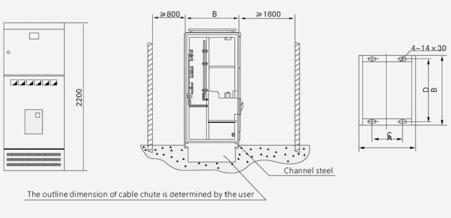
|
Universal cabinet code |
A |
B |
C |
D |
Note |
|
GCS-TG1010-4 |
1000 |
1000 |
850 |
956 |
Interconnection cabinet |
|
GCS-TG0810-4 |
800 |
1000 |
650 |
956 |
Receiving cabinet |
|
GCS-TG0808-4 |
800 |
800 |
650 |
756 |
Receiving cabinet |
|
GCS-TG0608-4 |
600 |
800 |
450 |
756 |
Receiving cabinet |
FIG 2 PC cabinet installation diagram
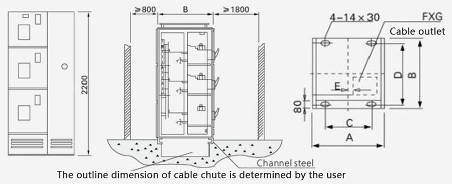
|
Universal cabinet code |
A |
B |
C |
D |
E |
FxG |
|
GCS-TG1010-2 |
1000 |
1000 |
850 |
956 |
1000 |
400×400 |
|
GCS-TG0810-2 |
800 |
1000 |
650 |
956 |
800 |
200×400 |
|
GCS-TG1008-2 |
1000 |
800 |
850 |
756 |
1000 |
400×400 |
|
GCS-TG0808-2 |
800 |
800 |
650 |
756 |
800 |
200×400 |
3 MCC cabinet installation diagram
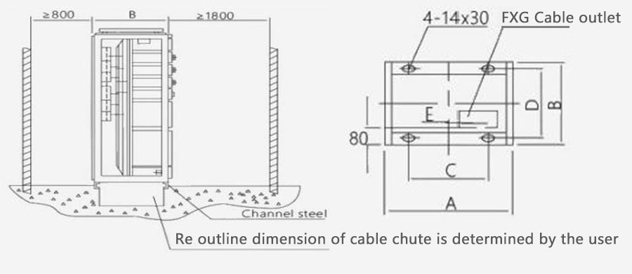
|
Universal cabinet code |
A |
B |
C |
D |
E |
FxG |
|
GCS-TG1006-1 |
1000 |
600 |
850 |
556 |
60 |
400×350 |
|
GCS-TG0806-1 |
800 |
600 |
650 |
556 |
160 |
200×350 |
Ordering instruction
The order contract includes the following contents:
● The full model of the product includes the main circuit solution number and auxiliary circuit solution number
● Main circuit system combination sequence diagram
● Auxiliary circuit schematic diagram
● List of components in the cabinet
● Voltage,current,time and other setting parameters in the circuit
● Other special requirements inconsistent with the normal use of the product
Hot Tags: GCS Low Voltage Withdrawable Switchgear, China, Manufacturers, Suppliers, Factory, Quality, Wholesale
Related Category
Send Inquiry
Contact Info
-
Address
No. 68, Wei No.19 Road, Yueqing Economic Development Zone, Yueqing City, Wenzhou City, Zhejiang Province,China
-
-
E-mail
For inquiries about Distribution Cabinet Shell, Circuit Breakers, Switchgear or price list, please leave your email to us and we will be in touch within 24 hours.


